Nondestructive Testing of Roads, Bridges, Tunnels, etc. Using Microwaves
Research Background and Objectives
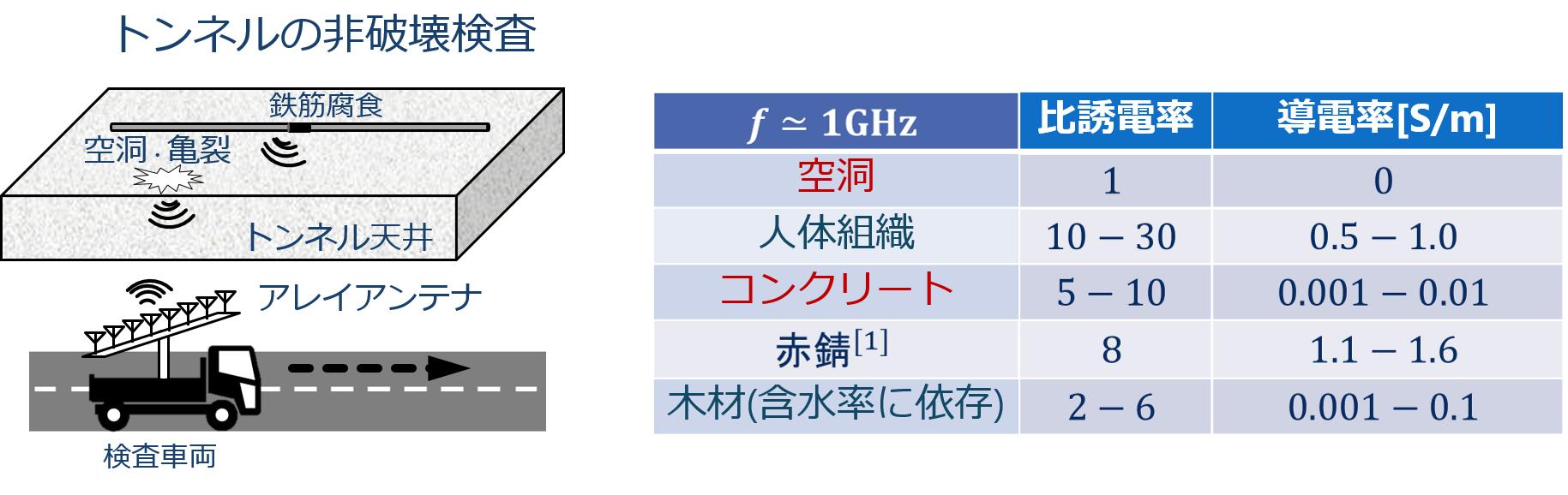
The total length of tunnels in Japan is more than 2300 km for railroads, 4100 km for roads, and dozens of times longer for expressways. Most of these tunnels were rapidly constructed during the period of rapid economic growth, and in recent years the risk of tunnel top collapse, bridge collapse, road cave-ins, etc. due to aging and earthquakes has increased significantly. Therefore, there is a great need for a technology that can quickly screen the interior of roads and other structures with a high defect identification rate. Conventional sounding and ultrasonic measurement methods require contact measurement, making it difficult to inspect large areas. Laser measurement can only detect surface delamination, and cannot identify cavities deep within the concrete, soil erosion, or corrosion of reinforcing bars. On the other hand, nondestructive inspection using microwaves enables non-contact measurement from a distance of several meters because spatial attenuation is negligible, and microwaves on the low frequency side (1-3 GHz) can reach a depth of 50 cm to 1 m inside concrete. Therefore, it is possible to monitor a large area in a short time by installing a transmitter/receiver module in a vehicle and acquiring scattering data while the vehicle is running inside a road or tunnel (Figure 1).
Quantitative imaging by inverse scattering priblem combining radar image
Conventional microwave inspection is mainly based on the radar method, but it is extremely difficult to identify properties such as cavities and rebar corrosion from images because it cannot extract information on complex permittivity. On the other hand, it is known that complex permittivity differs significantly among concrete, cavities, and rusted reinforcing bars (see the right side of Figure 1). Reconstructing the complex permittivity distribution with high accuracy improves the discrimination performance of the technique dramatically. On the other hand, the conventional tomography method has a problem that it does not provide sufficient accuracy, especially in nondestructive inspection models where the observation direction is restricted (element arrangement surrounding the object is not possible), due to its remarkable bad configurability (the number of observed data is very small compared to the number of unknowns). In response to this problem, we have proposed a method that integrates radar and tomography. Cavities and reinforcing bars have significantly different complex permittivity from concrete, resulting in strong reflected waves. Using these reflected waves, the position and shape of the structure can be approximately estimated using a radar-like method. The radar technique is the highly accurate RPM method. By narrowing down the ROI (Region of Interest), i.e., cavity and rebar, using the radar method, the number of unknowns in the tomography method can be dramatically reduced, and high accuracy can be achieved even in nondestructive measurement models, which are generally extremely difficult to obtain. Assume the numerical model shown in Figure 2. Inside the concrete there are small targets with complex permittivity corresponding to cavities and various types of rust. Figure 3 shows an enlarged view of the cavity. The reconstruction using only the tomographic method in the center of Figure 3 has very poor reconstruction accuracy due to the bad configurations described above, and it is difficult to identify the cavities. On the other hand, the right figure in Figure 3 shows the result of integrating the RPM method and the tomography method, and shows that by restricting the ROI and reducing the number of unknowns, the method retains high accuracy even for very difficult observation models and is useful for identifying cavities. Currently, the same method is being validated using actual concrete specimens, and research is being promoted, including ministry projects and joint research.
Shuto Takahashi, Katsuyuki Suzuki, Takahiro Hanabusa and Shouhei Kidera
"Microwave Subsurface Imaging Method by Incorporating Radar and Tomographic Approaches",
IEEE Trans. on Antennas and Propagation, (in press), 2022.
Takahiro Hanabusa, Takahide Morooka and Shouhei Kidera.
"Deep Learning Based Calibration in Contrast Source Inversion Based Microwave Subsurface Imaging",
IEEE Geoscience and Remote Sensing Letters, vol. 19, pp. 1-5, 2022.
The total length of tunnels in Japan is more than 2300 km for railroads, 4100 km for roads, and dozens of times longer for expressways. Most of these tunnels were rapidly constructed during the period of rapid economic growth, and in recent years the risk of tunnel top collapse, bridge collapse, road cave-ins, etc. due to aging and earthquakes has increased significantly. Therefore, there is a great need for a technology that can quickly screen the interior of roads and other structures with a high defect identification rate. Conventional sounding and ultrasonic measurement methods require contact measurement, making it difficult to inspect large areas. Laser measurement can only detect surface delamination, and cannot identify cavities deep within the concrete, soil erosion, or corrosion of reinforcing bars. On the other hand, nondestructive inspection using microwaves enables non-contact measurement from a distance of several meters because spatial attenuation is negligible, and microwaves on the low frequency side (1-3 GHz) can reach a depth of 50 cm to 1 m inside concrete. Therefore, it is possible to monitor a large area in a short time by installing a transmitter/receiver module in a vehicle and acquiring scattering data while the vehicle is running inside a road or tunnel (Figure 1).
Figure 1: Microwave concrete nondestructive inspection model (left); comparison of dielectric constants for various properties (right)
Quantitative imaging by inverse scattering priblem combining radar image
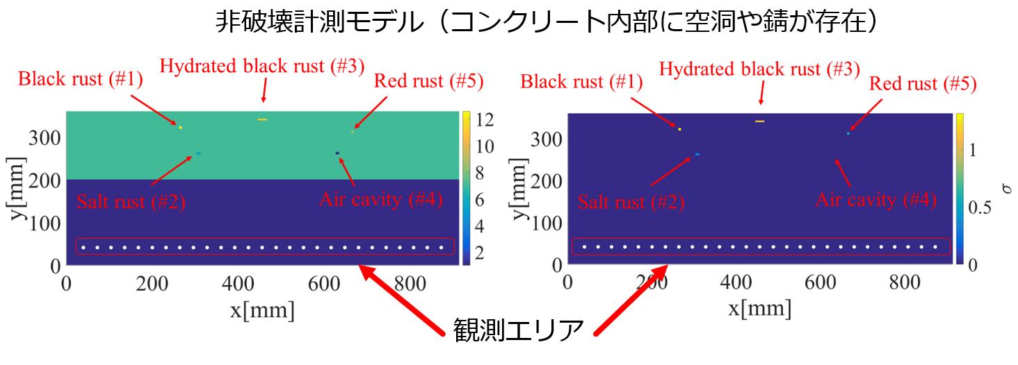
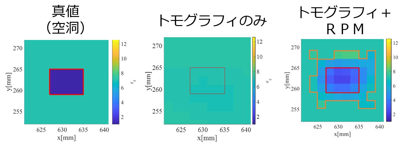
Conventional microwave inspection is mainly based on the radar method, but it is extremely difficult to identify properties such as cavities and rebar corrosion from images because it cannot extract information on complex permittivity. On the other hand, it is known that complex permittivity differs significantly among concrete, cavities, and rusted reinforcing bars (see the right side of Figure 1). Reconstructing the complex permittivity distribution with high accuracy improves the discrimination performance of the technique dramatically. On the other hand, the conventional tomography method has a problem that it does not provide sufficient accuracy, especially in nondestructive inspection models where the observation direction is restricted (element arrangement surrounding the object is not possible), due to its remarkable bad configurability (the number of observed data is very small compared to the number of unknowns). In response to this problem, we have proposed a method that integrates radar and tomography. Cavities and reinforcing bars have significantly different complex permittivity from concrete, resulting in strong reflected waves. Using these reflected waves, the position and shape of the structure can be approximately estimated using a radar-like method. The radar technique is the highly accurate RPM method. By narrowing down the ROI (Region of Interest), i.e., cavity and rebar, using the radar method, the number of unknowns in the tomography method can be dramatically reduced, and high accuracy can be achieved even in nondestructive measurement models, which are generally extremely difficult to obtain. Assume the numerical model shown in Figure 2. Inside the concrete there are small targets with complex permittivity corresponding to cavities and various types of rust. Figure 3 shows an enlarged view of the cavity. The reconstruction using only the tomographic method in the center of Figure 3 has very poor reconstruction accuracy due to the bad configurations described above, and it is difficult to identify the cavities. On the other hand, the right figure in Figure 3 shows the result of integrating the RPM method and the tomography method, and shows that by restricting the ROI and reducing the number of unknowns, the method retains high accuracy even for very difficult observation models and is useful for identifying cavities. Currently, the same method is being validated using actual concrete specimens, and research is being promoted, including ministry projects and joint research.
Figure 2: Numerical model (left: permittivity distribution, right: conductivity distribution)
Figure 3: Dielectric constant distribution of a cavity (left: true value, center: conventional tomography method, right: fusion of radar and tomography methods)